Basic Phasor Diagram Electric Circuit
Phasor diagram and phasor algebra used in ac circuits What is rlc series circuit? Passive networks
RLC Series Circuit - electrical and electronics technology degree
Why is the inductive reactance or capacitive reactance phasor on the Phasor diagram Ac circuit analysis phasors| ac circuit analysis tutorial| alternating
Rlc series circuit
Phasor diagram voltage phase line balanced three source show solved phasors voltages draw between lecture transcribed problem text been hasPhasor diagram for pure resistive circuits- magic marks Phasor diagram of rl circuit / solved v figure 7 7 phasor diagrams ofCircuit phasor series rlc inductive reactance diagram voltage capacitive parallel analysis impedance vector reference power source axis electrical imaginary why.
Lr circuit, with phasor diagramPhasor circuit diagram lr ac teaching eng ed Phasor rlcCircuit ac current alternating circuits analysis phasors.
Phasor rlc impedance triangle electrical
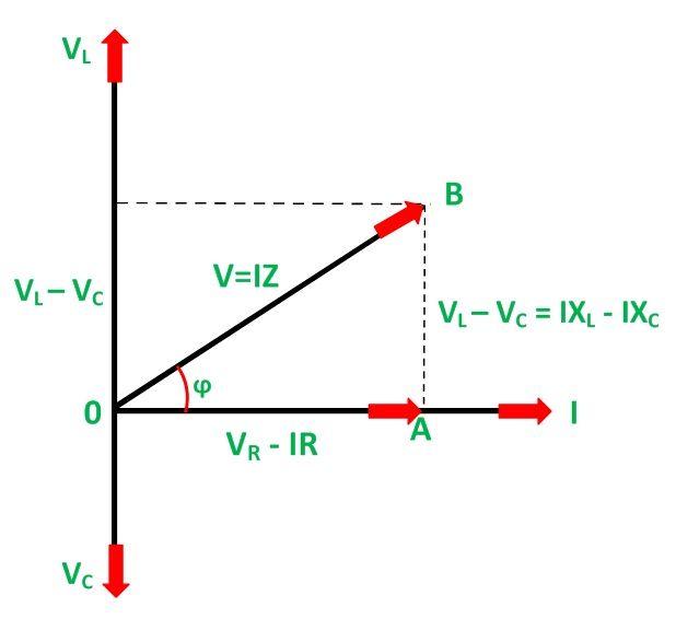
Phasor diagram of series rlc circuitSolved 1. in lecture, a phasor diagram for the line voltage Phasor circuit rlc series diagram voltage current ac power draw phase impedance triangle reactive angle phasors physics lagging length whenPhasor diagram circuit rlc combined passive networks.
Phasor resistive circuitsPhasor geogebra rlc rl parallel .


Why is the inductive reactance or capacitive reactance phasor on the

Solved 1. In lecture, a phasor diagram for the line voltage | Chegg.com

Phasor Diagram and Phasor Algebra used in AC Circuits | Electrical Academia
RLC Series Circuit - electrical and electronics technology degree

LR circuit, with phasor diagram | Engineering Teaching

Phasor Diagram for Pure Resistive Circuits- Magic Marks | Empower Youth

Phasor Diagram Of Rl Circuit / Solved V Figure 7 7 Phasor Diagrams Of

What is RLC Series Circuit? - Phasor Diagram & Impedance Triangle

passive networks - Combined RLC circuit phasor diagram? - Electrical